

Mechanical Components Matter in Medical Equipment Development
A diagnostic instrument depends on its mechanical structure as well as its sensors and software. Housings, brackets and fixtures position internal modules, support repeatable assembly and allow access for service. Their dimensions must match the approved design, especially where parts locate moving or sensitive components. CNC machining can support prototypes and production parts for non-patient-contact equipment when the drawing, material and inspection needs are clearly defined. The examples below are conceptual illustrations of component types, not photographs of a certified device or a completed customer project.
Example One Housing for a Benchtop Analyzer
An instrument housing may combine a milled cavity, mounting bosses, cable openings and a reference surface for internal modules. The drawing should identify which bores and faces control alignment and which dimensions are mainly cosmetic. This distinction helps plan machining and inspection around the parts that affect assembly.
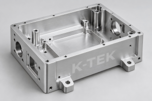
Figure 1. Illustrative CNC housing for a benchtop diagnostic instrument. K-TEK watermark.
For a prototype, review access for tools and fasteners before cutting material. Specify the material grade and any surface finish or coating requirements on the drawing; a visual image alone cannot establish suitability for the intended device.
Example Two Instrument Mounting Bracket
A mounting bracket links modules within a medical or laboratory instrument. Hole locations, flat mounting faces and locating features can determine whether the module installs without adjustment. When a drawing calls for close positional control, agree on the datum scheme and measurement method during quotation review. 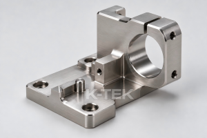
Figure 2. Illustrative machined bracket for instrument mounting. K-TEK watermark.
The bracket example also shows why the interface deserves more attention than an attractive finish. A part can look precise and still need dimensional verification at the features that define its fit.
Example Three Sample Handling Fixture
A sample handling fixture may use pockets, slots and locating pins to place containers or subassemblies consistently inside a benchtop instrument. Its geometry should reflect the mating components and the expected assembly sequence. For repeated units, an inspected first article helps confirm that the planned process matches the drawing. 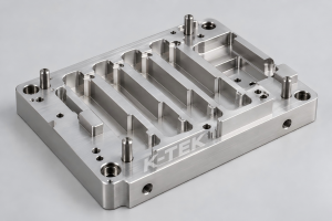
Figure 3. Illustrative sample handling fixture for laboratory equipment. K-TEK watermark.
If a fixture will contact samples or be exposed to cleaning agents, the customer should state those conditions so the material and finish can be reviewed for that project. The finished device manufacturer remains responsible for the applicable device-level testing and approvals.
What to Send for an Engineering Review
Send the current 2D drawing and 3D model, material specification, quantity, critical interfaces, surface finish and requested inspection records. Flag features that must be checked on the first article. A clear review helps identify process questions before the sample is made and creates a more useful basis for quotation. K-TEK provides custom CNC milling, turning and dimensional inspection for industrial components. To discuss a medical or laboratory equipment project, send the component drawings and intended requirements to k-teksales8@ktekpart.com. Capabilities and documentation can be confirmed for the specific part before an order is placed.
Author Information
Writer: Caylin | Date: September 29, 2026 Email: k-teksales8@ktekpart.com | Web: www.k-tekmachining.com
Post time: Sep-29-2026


